SIXTY SECOND TIMER PROJECT:
Project Overview
We have to design a digital sixty second timer that is able to count from 00 to 59. The design has two controls inputs and two output displays. The two inputs are Clock and Reset. The Clock signal is a 1 Hz square wave that controls the count rate. The Reset signal, when it is a logic zero, resets and holds the count as zero. When the Reset signal is a logic one, counting is enabled. When the count reaches sixty second, the counting resets at zero.
|
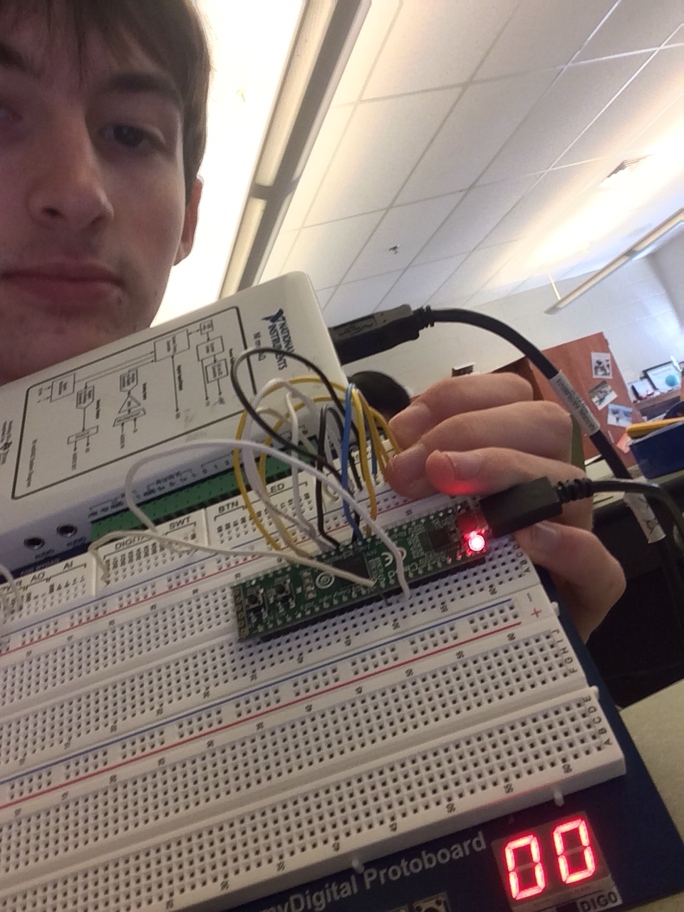
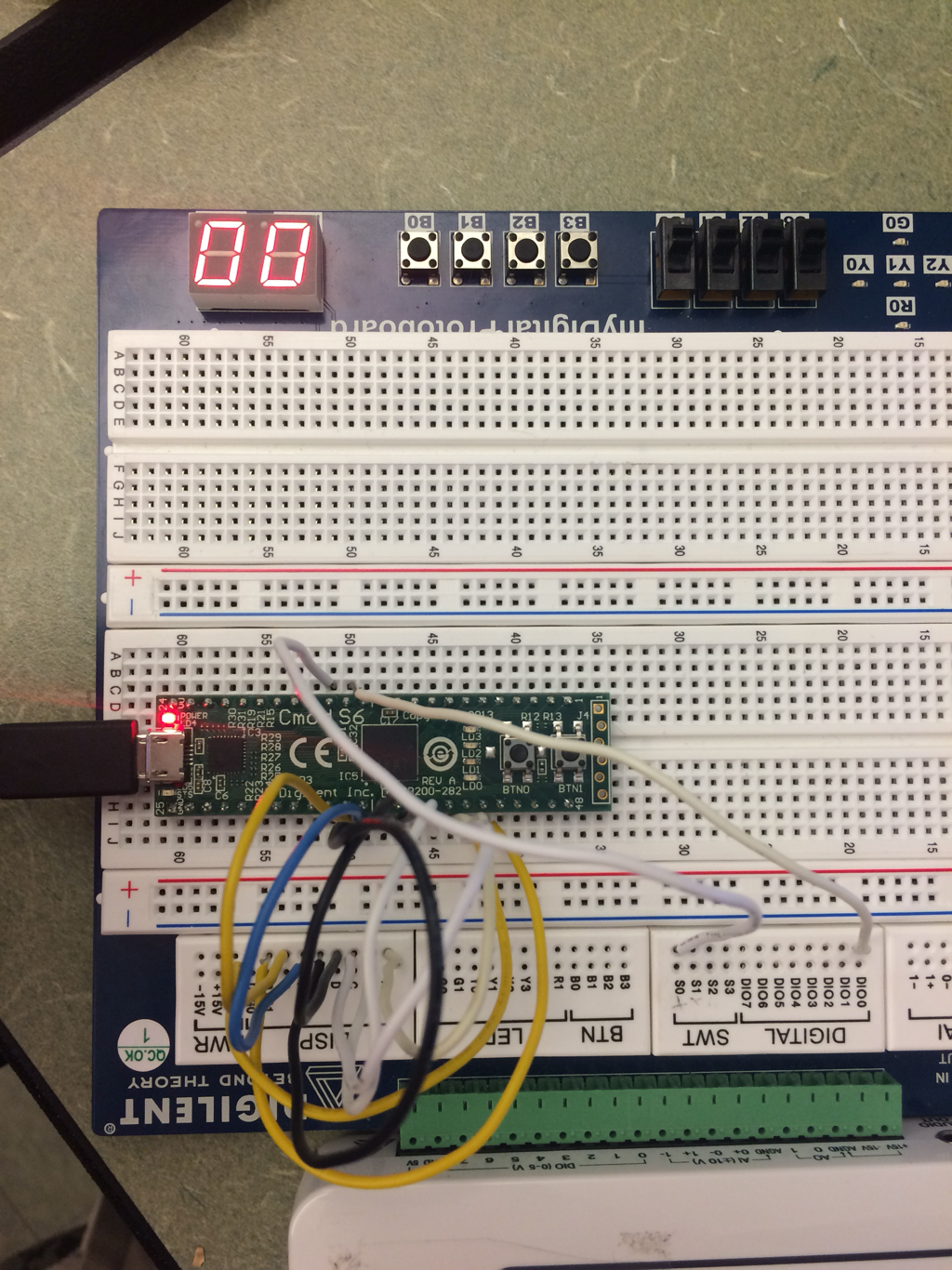
this is the breadboard
|
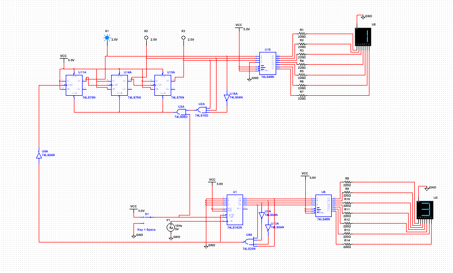
MultiSim Circuit
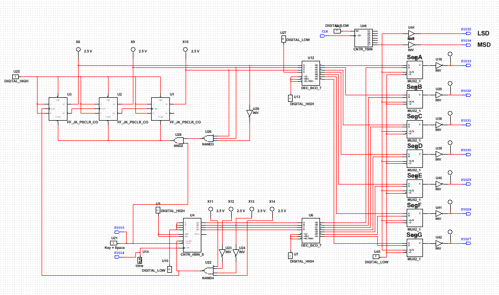
PLD circuit
This project is very similar to the DMV project from earlier in the year. Both require the circuits to count up to a number such as this project counting from 0 to 59 before resetting and the DMV project counting from 0 to 80 before resetting. They both used the same circuit layout as well as a similar layout of the reset switch, allowing the ones circuit to reset the tens circuit at a specified number. However This project uses a 74LS163 while the DMV project does not which changes up the way you have to wire the numbers for the ones circuit since it shows you the number that you wired on the display instead of showing you the number before the number you wired on the connected display.
Final Project Conclusions
The difference between synchronous and asynchronous circuits is that synchronous circuits are all wired to an external clock while for asynchronous circuits, every flip-flop after the first-flip flop is connected to the output of the flip-flop before it. So the first flip-flop is connected to the clock, then the second flip-flop is connected to the output of the first flip-flop which would be Q or NOT Q depending on whether its an up or down circuit.
The 75LS163 has no ripple effect like normal flip-flops and it displays the number that is wired to it, not the number before, however it is not able to count down. The 75LS193 is able to count down but the number that is wired does not show on the display, the number before that number will show up. So if you wire the counter to stop at 6 the display would stop at 5, not 6. The 75LS163 does not have this problem, if you wire a 6, the display will show a 6.
Building the circuit was pretty easy since it was very similar to our DMV project earlier in the year. Building the tens unit display is pretty easy since it was an up counter with 3 flip-flops that would go from 0 to 5 and then reset. The ones unit display was a little bit more tricky since you need to connect the CLR of the counter to the input of the tens unit counter like shown above. and then you would have to connect the clock from the tens unit to the CLR of the ones unit. But the LOAD had to start off at zero so you need to connect A,B,C, and D to ground while ENP and ENT are connected to power. Then the ones unit would have to go from 0 to 9 so you had to make the counter read a 10 since it displays the number before the number that is wired. So after doing that your input for the tens counter should have an AND gate connecting the input of the tens display to the CLR like said earlier. This would change the tens unit to the next number after the ones unit hits the number ten that is wired or the number nine that is displayed.
My classmates created circuits that were very similar to mine, they might have added another gate, or changed up the pin numbers or wired the counter input and output to be different. However other then those minor differences the circuits are pretty much the same.
