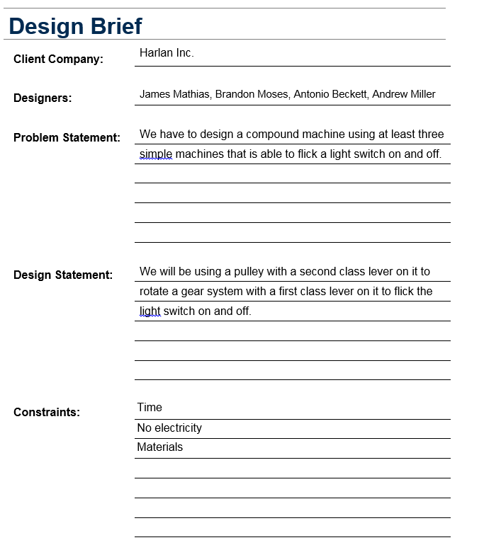
Design Brief
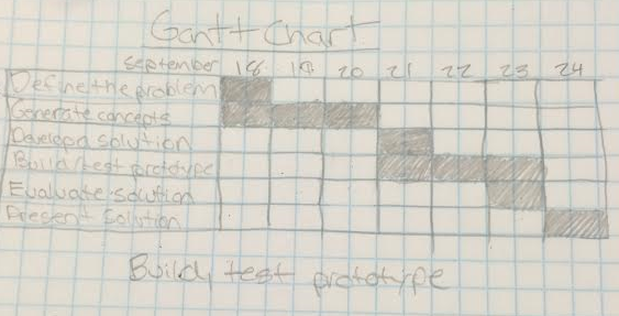
Gantt Chart
Decision Matrix
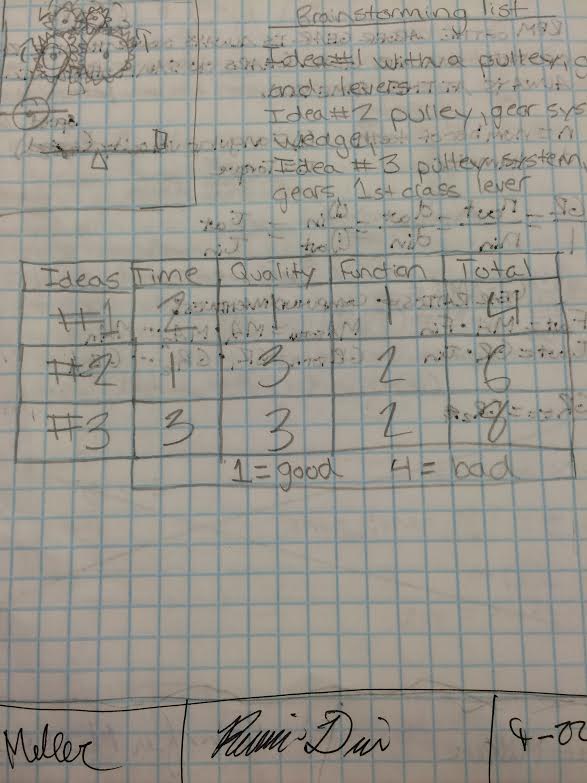
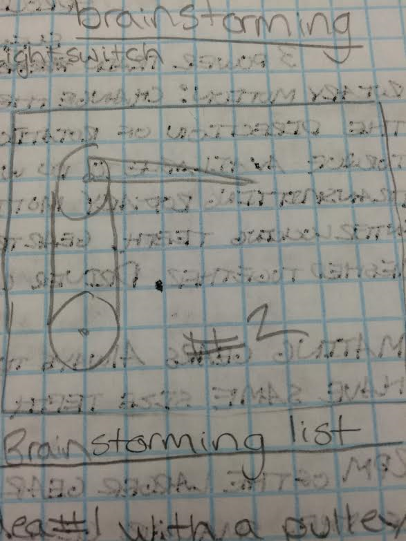
Brainstorming list:
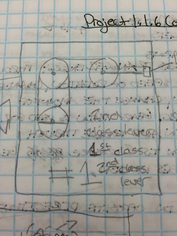
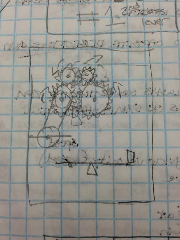
Sketch #1: Pulley system turns a gear system which in turn moves a second class lever up or down to turn off and on a light switch.
Sketch #2: A lever on one end of a gear system turns the gear system which in then rotates a wedge which causes the light switch to turn on and off.
Sketch #3: A first class lever turns a pulley which would turn a gear system which would drop a weight onto one side of a first class lever which would cause the opposite side of the lever to raise and turn on the light switch.
Preliminary sketches
|
|
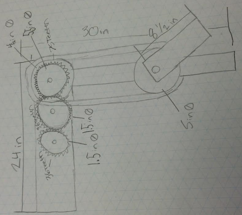
Final Sketch
Building process, test results and modifications.
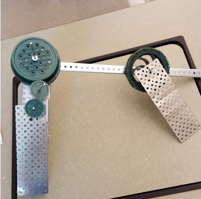
When we first started to build our machine we decided to go with idea number 1 with the pulley system, gear system, and second class lever. As we were building, we started to notice that the type of gears that we chose were not always connecting with each other and would cause the machine to stop working. So because of that, we tried to push the gears together using a rectangular piece of metal so that the gears would stay in place with each other. However after doing that we decided to test it on the light switch and soon found out that the gear system did not have enough torque to move the light switch using the gears that we had. So we decided to change the gears out with ones that could provide more torque so that we would be able to move the light switch. However we ran out of time so we did not complete the machine but if we did complete it by putting on another lever, adding support to the gears, and adding a couple more gears to the machine I believe that our machine would have been able to move the light switch.
Final Design Picture
Final Calculations
Mechanism 1 Type: Pulley system - GR = Tout/Tin, GR = 75/36= 12/25, GR = 2.08
Mechanism 2 Type: IMA = # of strands, IMA = 2
Mechanism 3 Type: IMA = DE/DR, IMA = 3/8.5, IMA = .35
Mechanism 2 Type: IMA = # of strands, IMA = 2
Mechanism 3 Type: IMA = DE/DR, IMA = 3/8.5, IMA = .35
Conclusion Questions
1) The mechanism that was the easiest for me to determine the mechanical advantage of would be the second class lever because all I needed was the distance of the effort and the distance of the resistance.
2) The gear system was the most difficult out of the three machines to calculate the gear ratio because it had more then two gears and it was confusing on which gear I should pick since two out of three of the gears are the same size and the input was bigger then the input gear.
3) The values that I came up with for the input and output forces of our machine would be a effort of around 15 or 16 pounds of force since the machine requires a lot of effort to turn the gears and keep the machine stable and provide support.
4) If there were any modifications that we could make with our machine, it would be to add more gears to increase torque, more support for the gears, and a better pulley system for the machine.
