The Lone Ranger:

Project Description:
The wires have nothing to do with this project by the way, it's just a really good picture.
In this project we were required to design a frame assembly for a motor mount structure for a Lycoming 0-300 to be installed in a light aircraft. There were a total of 5 constraints given to us.
1) The large plate represents the aircraft firewall as shown in the image below. This must be grounded as the stable part of the frame. Use fixed constraints on the six firewall to structural member attachment points.
2) The structure will support one Lycoming O-300 engine (250 lb) attached at the three points.
3) The structure will be loaded with negative 3 G and positive 6 G which is simulated by exaggerated engine weight due to sudden aircraft acceleration or a change in altitude.
4) The structural members will be 1 1/2 in. ANSI pipe.
5) Frame members should be mitered as necessary.
So with these constraints we were asked to calculate the forces that must be simulated with the positive and then the negative G loads. Label the frames below with the forces that will be modeled for each loading condition. Also label the structural members below as compression or tension. Predict where the critical point will be for each loading condition. To do this we used Autodesk Inventor to create the model of the frame design that we were given. The we were required to conduct a frame analysis to ensure that the frame meets design specifications.
Procedure:
|
To prepare for this project we did two tutorials that helped us become more adept at using the specific tools that this project required. I do think that the tutorials helped but I also believe that it could have been a little better or if we could have an example on paper to keep so that we can look back on that paper for reference. We also did a materials investigation, which showed the cost, pros and cons, and how strong that material is when it is being stretched and compressed.
|
Designing the engine mount was pretty easy because we were already given the sketch of the frame to build upon so the only thing I had to do was decide the best material for the beams connecting the aircraft firewall to the three engine plates. So I decided upon stainless steel beams because steel is very strong in both compression and stretching, and the reason that I went for the stainless aspect was because stainless steel takes a very long time to begin to rust from water and it looks really cool so points to both.
|
|
To polish up the connecting pipes I used miter joints to 0.00 in to get a nice flat and even surface for the pipes to be as nice as possible if they were to be welded together. I also use trim to face bring the pipes back into normal physics because before I trimmed the pipes they were magically going through the airplane firewall which is beyond my understanding of physics. So I trimmed them to bring them into our understandable physics and so that they would look normal.
|
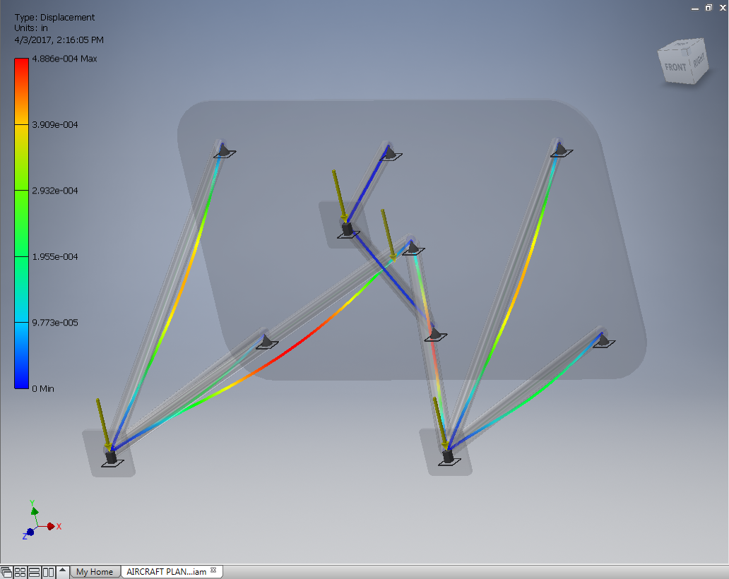
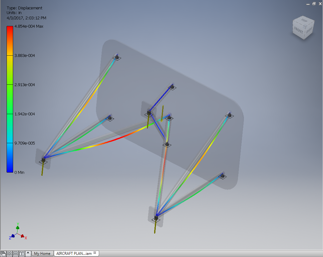
Below in the SOLUTION section there are two pictures. The right picture, and the left picture. The left picture has 3 forces of 250 lbs going in the same direction as the gravity is. And as you can see, the 3 forces are placed on the connecting point of the engine mount and the engine itself. The picture on the right is showing 3 forces of 500 lbs going opposite of the direction that gravity is going in. Why are the forces going in different directions you may ask. Well that is because the picture on the right as the simulation of a Positive 6 G title. The positive means opposite of gravity because since gravity starts down it is negative but to make it positive you would have to flip it to be opposite of itself. But in this case we changed the forces instead, I'm assuming that is because we want to simulate the plane being upside down, but it's just a theory. The 6 means double the amount of weight, so instead of just 3 forces there would 6, or in this case double the amount pounds on the already existing forces. The G just means gravity. In comparison the picture on the left is titled, Negative 3 G.
|
Solution:
|
What are the pictures down below? Well those are what is called Stress analysis. And it does exactly what the name says. It shows you the amount of stress on a given frame based on given forces so that you can analyze how structurally sound the mount is.
|
Once again just In case you forgot (hopefully not) I used stainless steel because it is strong in compression and stretching as well as it is very resistance to rusting.
|
The design below meets the specified constraints listed above because When building I made sure to follow the constraints exactly and correctly before moving on to the stress analysis.
|
|
|
This is the stress analysis of the frame with Negative 3 G
|
This is the stress analysis of the frame with Positive 6 G.
|
In the big paragraph above the picture on the right I did explain the what the Negative 3 G and the Positive 6 G means in terms of the stress analysis.
Conclusion:
As I was doing this project I learned quite a few things to help me later in my engineering career. I learned that the materials associated with building a product are a big factor in both the cost and structural stability. I also learned how to do a stress analysis to test how applied forces will effect the designed product. And I gained more knowledge of how to use more options to help design products such as using trimming and miter joints.
What were my contributions to the team. Well I decided that doing this project alone will be best for me since I started a day late and I shouldn't hold anyone up with trying to explain to me how to do all of this. So I did everything for this project. Just me.
I do believe that the frame generator is a useful tool for aerospace engineers because it allows you to create a frame whether its for the fuselage or the wing or the engine, and then analyze the stress that is being put on that frame from forces set by you. It basically allows you to simulate real life forces and how they would affect the plane while it is flying.
