Project 2.1.1 Majority Vote:
Project Overview:
What is the purpose of the circuit designed in this project?
We are doing this project to learn as well as show circuits and how to design and build them on both software and using real materials. Some constraints that we had were that we were only allowed to use 2-input gates which made the circuit bigger then if we could use 3 or more input gates. We have to create a voting machine that allows fair votes to be cast, more importantly when there is a tie between the voters (president, Vice President, secretary, and treasurer.) the president's vote determines the outcome.This report will give a general explaination and example of a circuit of a voting machine for majority votes.
|
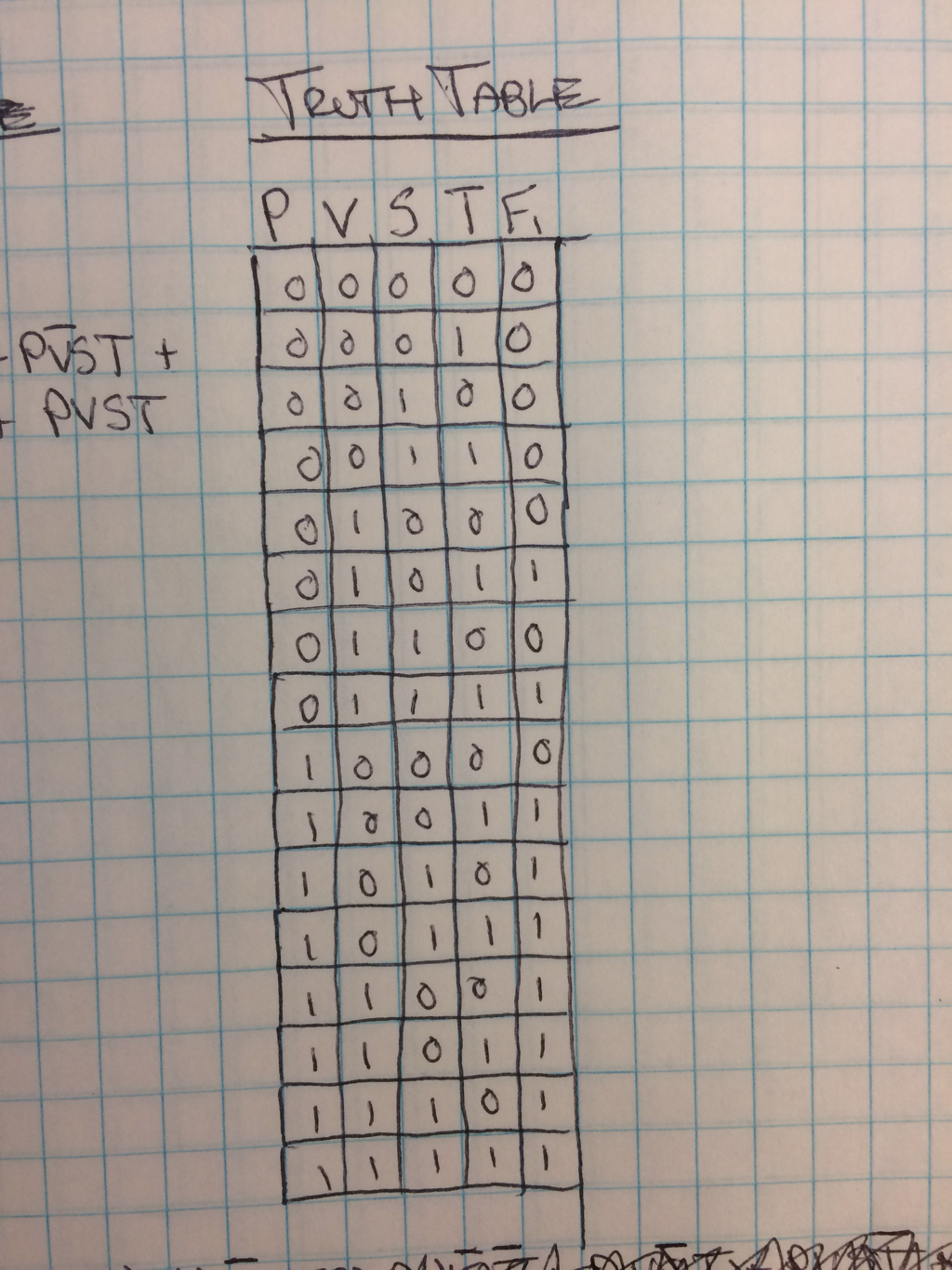
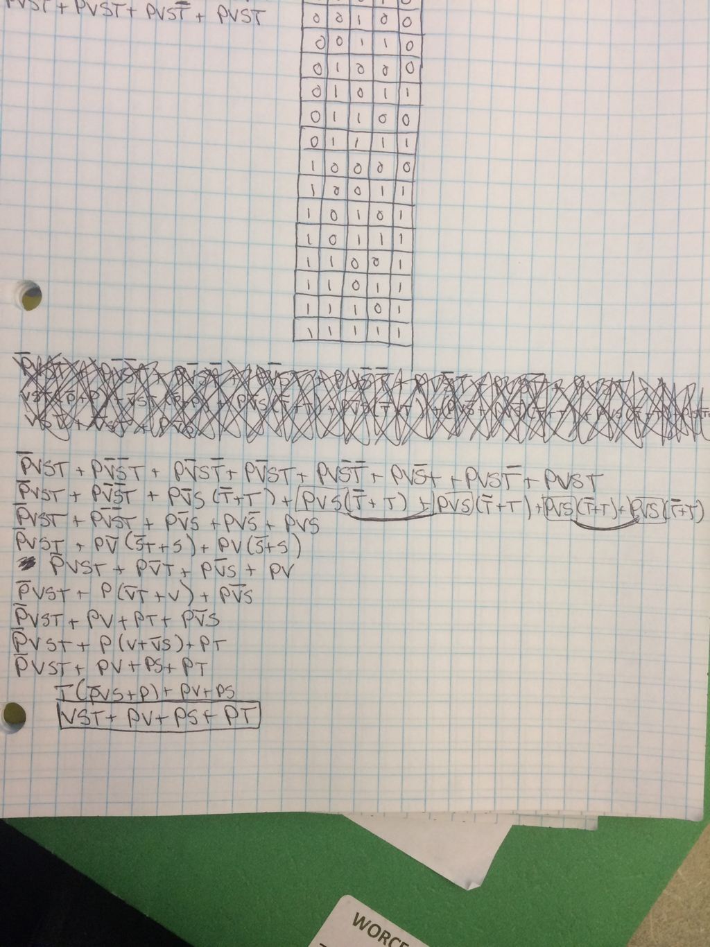
What is this to the right?
This is a truth table and it can be described as a graphical form of the logic expression or of the vote passes which is a one and if the vote doesn't pass which would be zero. On this specific truth table there are 4 variables (P, V, S, T) which means that it is 16 rows down and 5 rows across. For example if it was 2 variables it would be 4 rows down and 3 rows across since there are 2 variables it would be 2^2 which multiplies to 4. If there is a tie vote where 2 members vote one way and another member votes the other way so that the president decides if the vote goes one way or another. 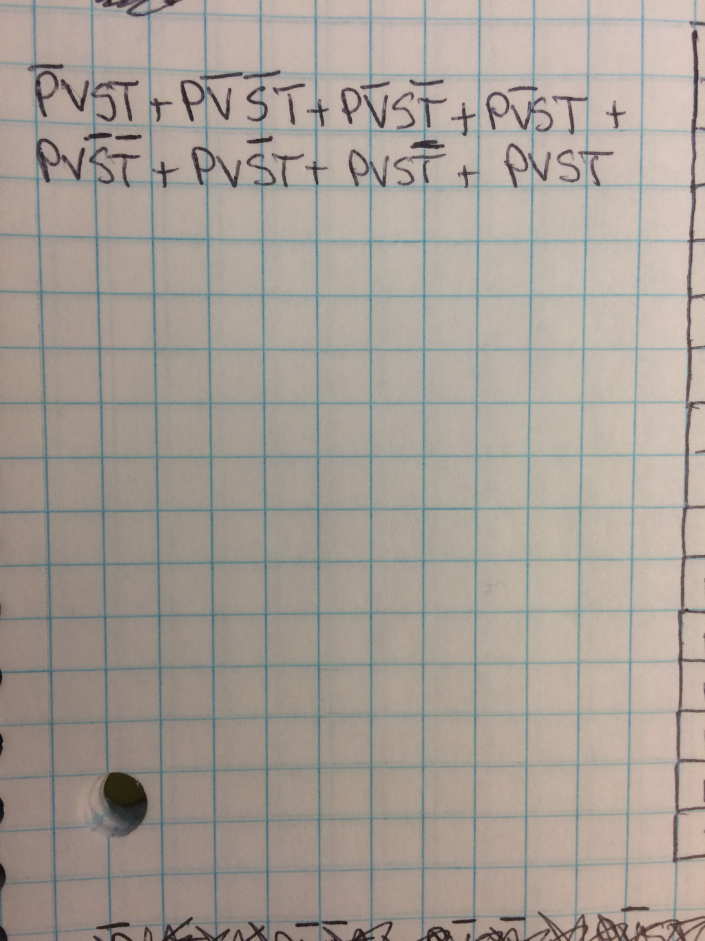
un-simplified expression and why it was chosen.
I decided to go with the SOP form because it is easier to look at and understand what is happening then if you would look at the POS form. And SOP stands for sums of products and POS stands for products of sums. |
Problem Conception via Truth table and Un-simplified Expression:
Un-simplified Circuit:
|
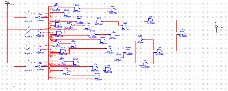
What is this? This is a un-simplified circuit in bus form, and the bus is that long line down the middle of the circuit. There are a total of 25 AND Gates and 6 OR Gates and 4 Inverters. The AND Gates create the multiplication part of the logic expression and the OR Gates create the addition part of the logic expression. So 9 AND Gate chips, 2 OR Gate chips and 1 inverter chip are required. |
|
Boolean Algebra Simplification:
The Boolean Algebra Simplification expression is a simplified version of the un-simplified logic expression given about. It is simplified using Boolean Algebra Formulas.
Simplified circuit
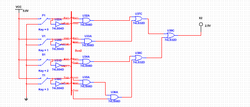
The simplified circuit above is in bus form and requires 5 AND Gates, 3 OR Gates and, 1 inverter. So 2 AND Gate chips, 1 OR Gate chip and 1 inverter Gate chip are needed. This version uses 7 less AND Gates and 1 less OR Gate then the un-simplified version of the circuit.
Bill of Materials
For the simplified version of the circuit i used 2 AND Gate chips and 1 OR Gate chip on the circuit board and had a total count of about 34 to 36 wires were used to build the working circuit if you count the two connecting wires that bridge the positive and negative areas of the circuit board.
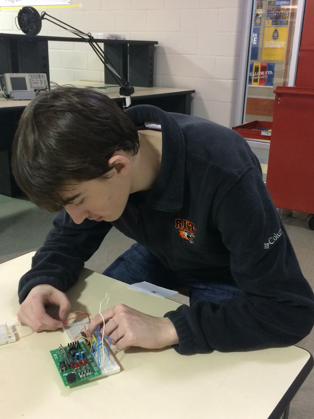
Here you can see me working on my bread board and the other two pictures are of the breadboard itself. The darker more yellow picture is of when it was being worked on and tested and the other more lighter picture is when it was completed and working. Working on this I made the mistake of moving the outputs of the wires to the wrong area of the chips thinking that I was putting the outputs into the input of the chips when I actually wasn't. So I troubleshooter and found out that the I had the wire outputs reversed for the inputs on the chips.
Conclusion
I think during this project I learned that the most important thing to do when building a circuit is to first understand what you are doing and then pay attention to what you are doing. I made the mistake of not fully paying attention to what I was building on my circuitboard and I messed up twice on the building part which costed me much needed time. So I learned to pay attention to what I was doing. This project shows how much work and time goes into building a simple circuit as well as teach us the specific parts of circuits that are used in real life for tasks ranging from turning lights on and off to breaking ties between the President, Vice President, Secretary, and Treasurer. To go from a project design to a finished circuit it requires that you known about electronics and how the wires and Gates work in relation to each other as well as in-simplified and simplified logic expressions and truth table and how to go from one to the other using Boolean Algebra. Boolean Algebra is the most useful here because it greatly simplified the logic expression down from a messy looking circuit to a very clean easy to read circuit that saves on time and materials then the original logic expression and it's circuit.
