Project Overview:
In this project we have to design a digital circuit that is able to display the count from 00 to 80. The design would have two control inputs and two output displays. The two inputs would be the Next and Reset Buttons or switches. The Next button, when pressed, advances the display by one. The Reset signal, which is also a button, will reset the display to a count of 00. When the display reaches the count of 80, the counting will stop. ( In this case, the employee at the check in counter will take a break and a new employee takes over the counter after the 80th customer is served.
|
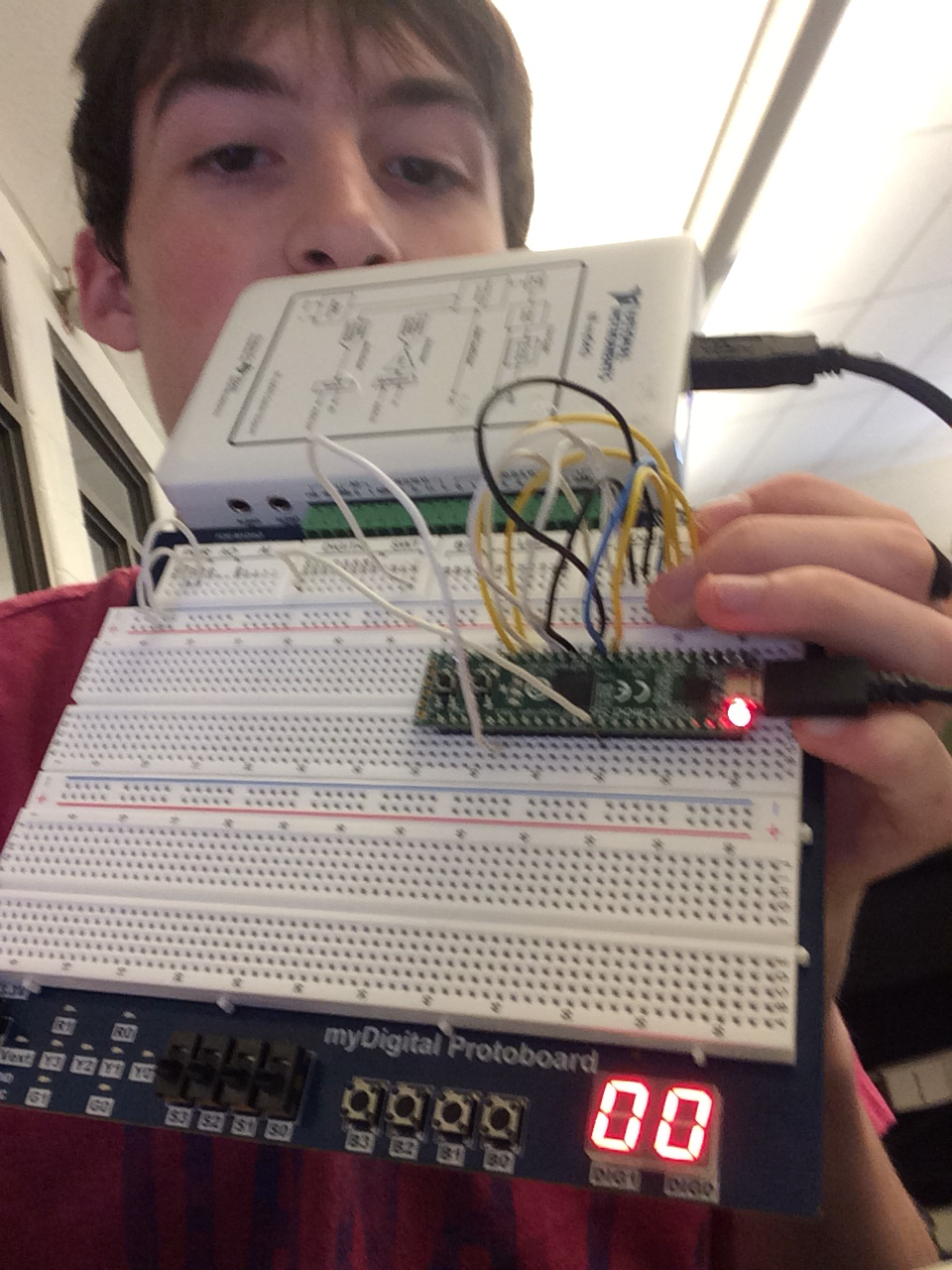
this is the breadboard.
|
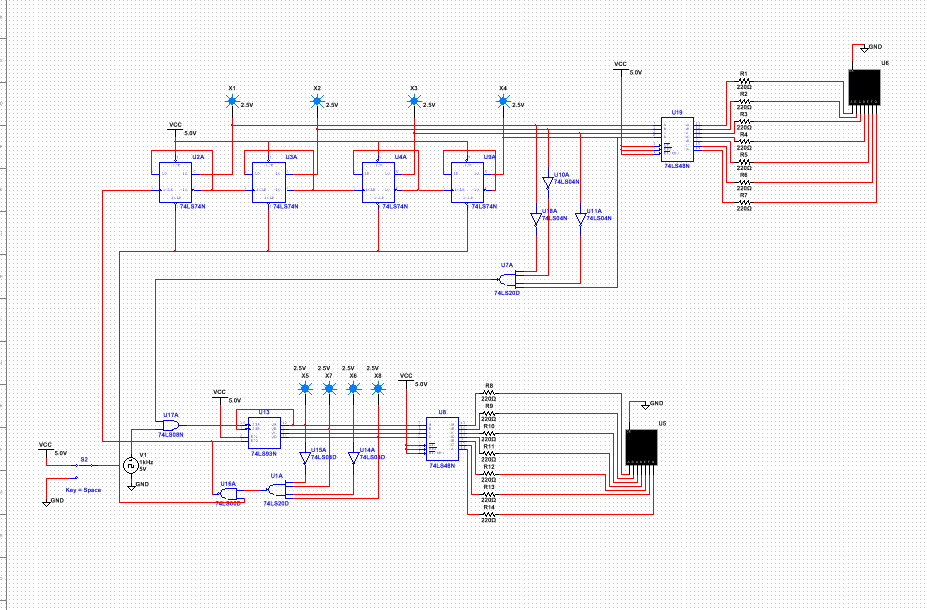
Multisim Circuit
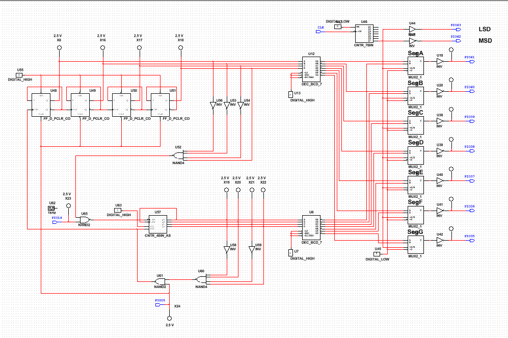
PLD Circuit
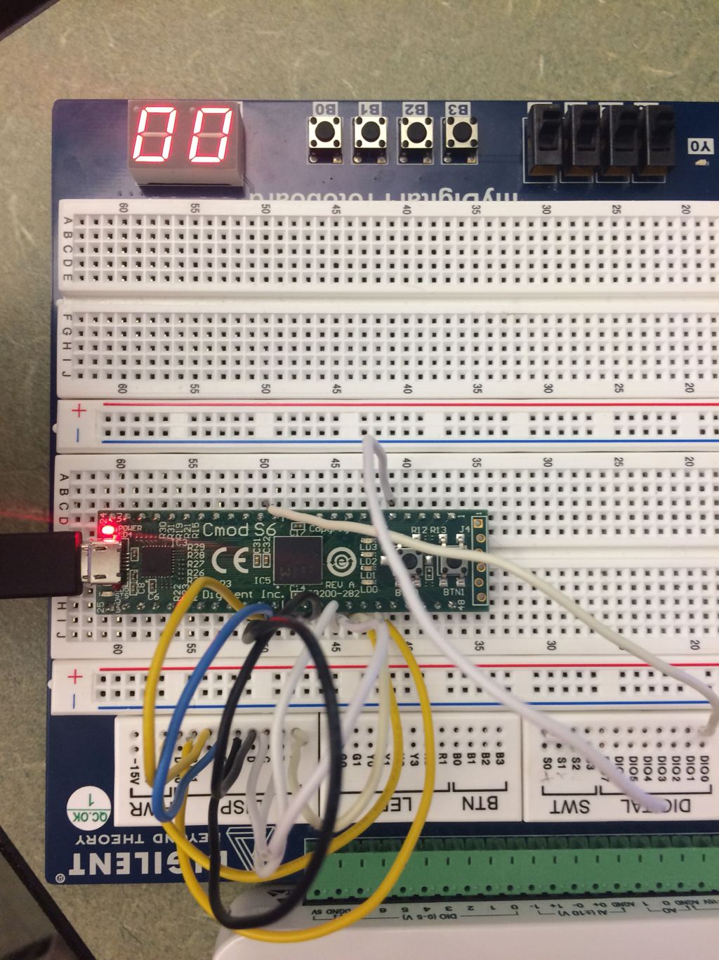
This is showing a close up view of the locations of where the wires are connect to the breadboard for a more accurate side by side comparison between this picture and the PLD picture up above.
Bill of Materials
13 wires were used as well as 1 chip. 11 are shown in this picture but there are two more in the ground and power farther right on the breadboard that provide power to the board itself.
Final Project Conclusions:
What is the difference between SSI and MSI circuits?
SSI stands for "small-scale integration" and it has less than 100 components to it which is about 10 gates. MSI which stands for "medium-scale integration" contains less than 500 components and has more than 10 but less than 100 gates in total.
SSI stands for "small-scale integration" and it has less than 100 components to it which is about 10 gates. MSI which stands for "medium-scale integration" contains less than 500 components and has more than 10 but less than 100 gates in total.
What is the limitations of the MSI circuit that I created?
To display two numbers at the same time it has to flash the numbers extremely rapidly to show the illusion of displaying two numbers at the same time, even though there is actually only one number being displayed at one time and not two.
To display two numbers at the same time it has to flash the numbers extremely rapidly to show the illusion of displaying two numbers at the same time, even though there is actually only one number being displayed at one time and not two.
What is the meaning of the "ripple effect"?
The ripple effect is a nickname for the delay caused between multiple flip-flops. The ripple effect is caused from delay caused by flip-flops after the first flip-flop, having their clock change based on the output of the first flip-flop, which causes a random delay.
The ripple effect is a nickname for the delay caused between multiple flip-flops. The ripple effect is caused from delay caused by flip-flops after the first flip-flop, having their clock change based on the output of the first flip-flop, which causes a random delay.
To do this I first created the two circuits that would eventually become the ones and tens unit circuit displays. Then I connected the tens unit clock to the ones unit so that it could then be reset by the ones unit circuit once the ones unit display reaches the number 10. Then I connect the tens unit circuit display to be wire from 0 to 8 and the ones unit circuit display to be wired from 0 to 10. This would allow the circuit to count up to 80 before resetting back down to 00. And then I added a reset key to the clock CLR which would reset both the tens and the ones display back down to zero when it is pressed.
Most of my classmates had very similar designs other than some minor differences such as different pins or the way they set up there gates.
