Project 2.5.3 Copier Jam Detector
Project Overview:
In this project the assignment is to design a logic circuit that will detect a paper jam in a copier. We will implement this design on the Digital Logic Board's Field Programmable Gate Array. As the paper passes through a copy machine, three photo sensors monitor its path. The photo sensors consist of a phototransistor paired with an incandescent lamp. When a paper breaks the light beam between a phototransistor and the incandescent lamp, the photo sensor outputs a logic one (1). When the beam is not broken (there is no paper), the photo sensor outputs a logic zero (0). Under normal operations paper will pass through the sensors such that adjacent sensors will not simultaneously detect paper. If they detect paper, this indicates that a paper jam has occurred. When a paper jam occurs, an LED indicator light will turn on an a buzzer will sound. The LED indicator will go off as soon as the jam is cleared. The buzzer should continue to sound until a reset button is pressed. This last condition requires that the output controlling the buzzer be latched with a flip-flop.
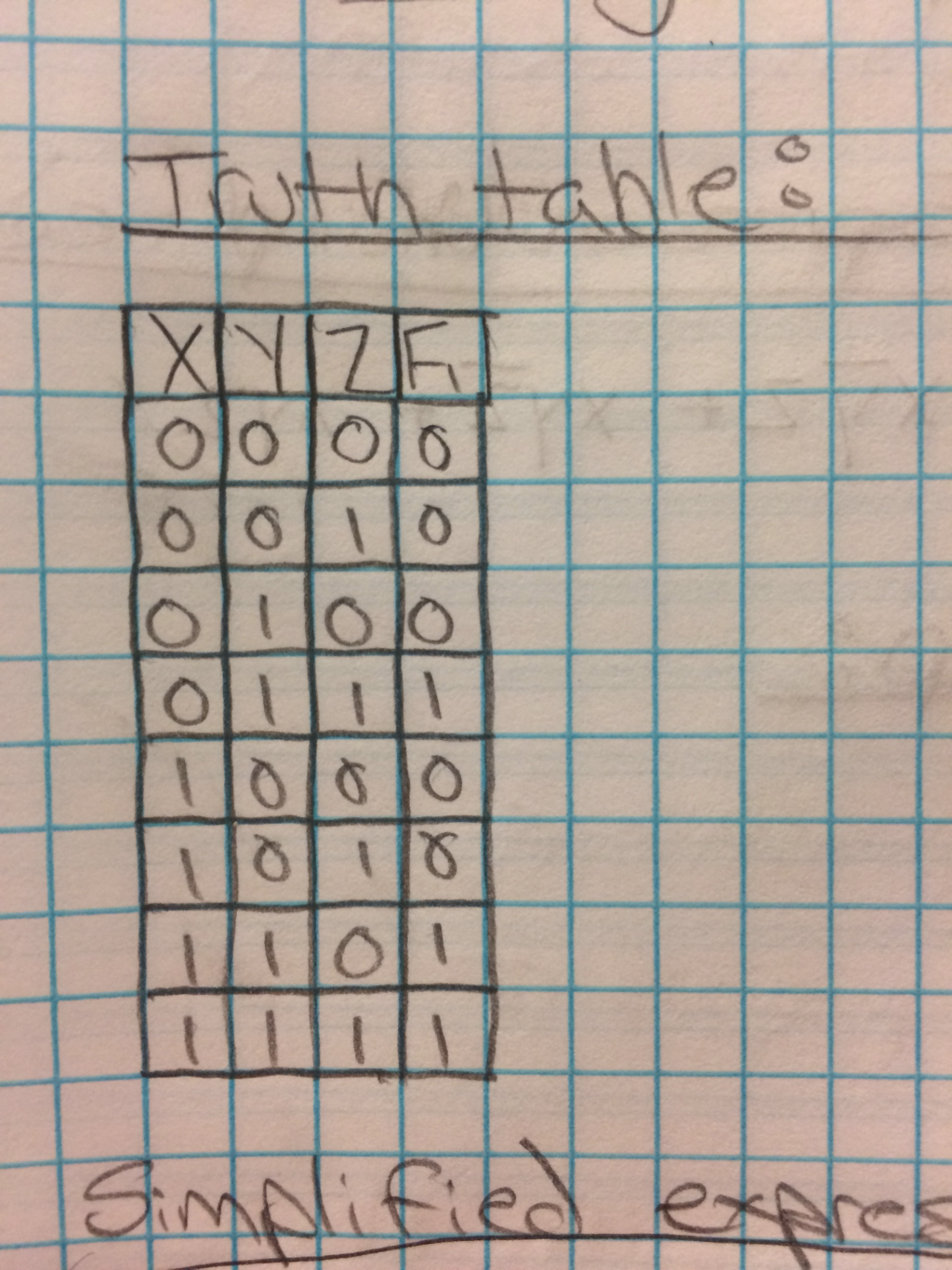
Truth Table:
|
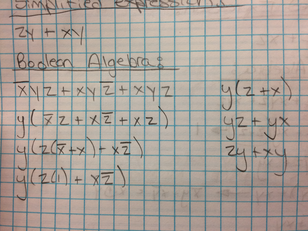
Boolean Algebra:
|
Un-simplified expression

K-Map:
|
Simplified expression:

|
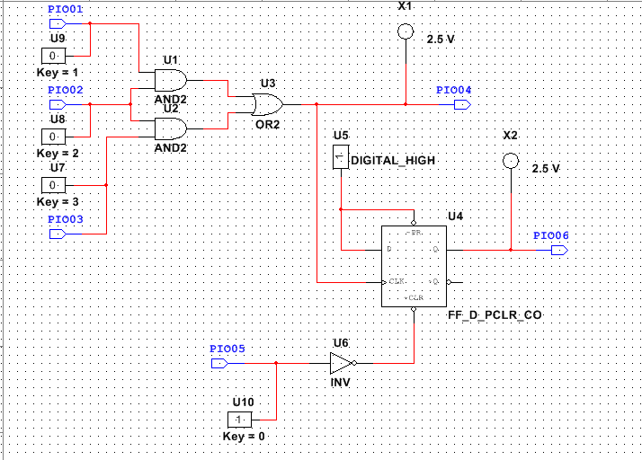
Circuits
PLD wiring:
Why resistors?
resistors help to limit the flow of power to the components of the build.
resistors help to limit the flow of power to the components of the build.
What is the purpose of combinational logic circuit?
It is able to do Boolean Algebra which helps to simplify the circuit and expression. And it can keep an output on while changing another output to be different.
It is able to do Boolean Algebra which helps to simplify the circuit and expression. And it can keep an output on while changing another output to be different.
Why do we have a flip flop?
It allows the buzzer to stay on even if the paper jam is fixed and the light goes off. This would get the employees attention even from a distance because of the buzzer.
It allows the buzzer to stay on even if the paper jam is fixed and the light goes off. This would get the employees attention even from a distance because of the buzzer.
Why LED goes off, but buzzer stays on?
The buzzer stays on because it is not wired to go off when the 3 inputs tell it to go off. When the 3 inputs turn the LED on the buzzer is wired to turn on. However, when the LED goes off, the buzzer will stay on. This is because the buzzer is turned off by a separate reset switch that controls the CLR or 0 input of the flip-flop.
The buzzer stays on because it is not wired to go off when the 3 inputs tell it to go off. When the 3 inputs turn the LED on the buzzer is wired to turn on. However, when the LED goes off, the buzzer will stay on. This is because the buzzer is turned off by a separate reset switch that controls the CLR or 0 input of the flip-flop.
Anything else that you find relevant.
This project was pretty easy for me to do, the only hard part was figuring out how to get the LED and buzzer to turn on the same time, but turn off differently then each other.
This project was pretty easy for me to do, the only hard part was figuring out how to get the LED and buzzer to turn on the same time, but turn off differently then each other.
Conclusion
How is this project different from the ones we have completed up to now? What did you learn?
This project is different because it doesn't use a digital display in it like the other projects nor does it use a 74LS48 in it. It is also much easier to do then the other projects. I learned that as long as you understand how the wiring works in both the simulation and while building, doing these projects are not hard at all because you know how everything will work together.
This project is different because it doesn't use a digital display in it like the other projects nor does it use a 74LS48 in it. It is also much easier to do then the other projects. I learned that as long as you understand how the wiring works in both the simulation and while building, doing these projects are not hard at all because you know how everything will work together.
To do this project I first decided to go with the truth table. The truth table needs to have 1's in the output area for every combination that involves two or more ones next to each other in the inputs. So if X and Y are ones and Z is a zero the output would be a 1. However, if X and Z are ones and Y is a zero that the output would be a zero since there are no adjacent 1's in the input section of the truth table. After completing the truth table you are able to get both the Un-simplified logic expression and the K-Map. Using the Boolean algebra you are able to get the simplified logic expression and use that to check to make sure you have the correct K-Map which in this case would be 2 by 4 box. 2 being across and 4 being down for a total of 8. So from left to right and back again, you should have 00011100 even though in the truth table it says 00010011. The change is because the fifth and sixth numbers switch places with the seventh and eighth numbers. Then you are able to build the circuit from the expression, ZY+XY. Building would only require 2 AND Gates and 1 OR Gate to connect to the input of paper machine. Then you need to use a D flip-flop to create the input and output for the buzzer. After doing all of that you should have a LED that turns on when 2 adjacent switches are turned to an output of 1. The buzzer should turn on with the LED but not off. The buzzer should have a separate reset switch to turn it off. And then you should have your circuit complete and ready to go.
